Large parts, such as the engine block of emergency generators, construction machinery or ship engines; truck steering knuckles; or gears and bearings used in wind generators are usually too large and heavy to be performed on fixed roughness measurement equipment Measurement. Nevertheless, the roughness parameters must still be tested. In fact, roughness measurements on large parts are often critical and difficult to perform. In most cases, it may require a lot of operator involvement and skills to hide the hidden surfaces in many features on the part.
These requirements are usually tried by skilled machinists (rather than skilled quality technicians) and often require a lot of effort. For example, on a large plane, the measurement may be simple and requires little skill. However, since the user cannot find the same precise measurement position with the naked eye, the repeatability of the measurement fluctuates greatly. To perform critical roughness measurements in an inclined, vertical (or upside down) overhead position, the drive unit or roughness measurement system must be fixed during the measurement, otherwise the measurement results will be incorrect.
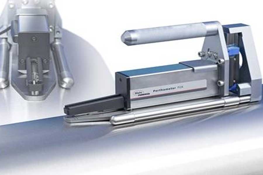
Fortunately, there are many portable surface finish measurement systems designed to bring gauges to parts. The above-mentioned problems can be solved by designing and using special portable fixtures, which can ensure that the drive unit is fixed during the measurement, so as to achieve reliable roughness measurement. If the test instruction defines the measurement position, the fixture can use positioning to ensure the correct position. You can also use part reference features to design the template to be located on the part to ensure that the template is located at the same point on each part.
In order to measure deep holes or interruptions in crankshaft and camshaft holes (for example, holes in large engine blocks), special fixtures (for positioning and locking the drive and probe) can be provided. In this case, the measuring head will measure the roughness of a single crankshaft bearing by placing the probe in the first measuring position controlled by the movable top ring. Next, the air switch activates the locking clamp to firmly position the probe, and then take the first measurement. Then release the clamp and move the clamp to the next stop ring position, and then clamp and measure. Repeat this operation for each crank position.
However, there are actually hundreds of surface finish parameters, and not all surface finish parameters can be measured with a simple roughness probe. Many of these parameters involve the expression of longer contour waves, which are the result of the machining process itself.
For these parameters, a non-slip probe is required. The non-slip probe incorporates a smooth, flat inner surface as a reference, so the probe can respond to waviness and roughness. Therefore, when specifying the waviness mark for OD, the alignment of the probe becomes critical. If the axis of the part is not aligned with the reference surface in the anti-skid sensor, when the probe passes over the top of the part, it looks like a curved surface compared to the reference of the probe. It is difficult to distinguish the curve of the crown from the long-wave surface irregularities in the part by the eyes alone. Although it is simple to perform this alignment on a table-mounted surface finish system, it is not the case for some large shafts with critical finishes.
Suppose we are trying to inspect a large printing roller. One can grasp how short-wave surface finish becomes a problem. The peaks and valleys of these short waves may cause too much ink to stick to the roller, or it may not be enough. On the other hand, if the short-wave finish is good, but the long-wave high and low points (contour problems), there may not be proper contact between the rollers or the paper. This is the key to the analysis of large OD. It is also important to ensure that the probe of the test part is fully aligned with the part.
Analytical drives tend to be quite large, especially when they require long traces. Trying to manually maintain the system and align it with the axis of the part while maintaining stability is a daunting effort. Here, simple and effective fixtures can make the user’s work much easier. Adding an alignment accessory to the surface profile drive ensures that the probe follows the top of the part and provides accurate and repeatable results.
Link to this article: How to measure the surface roughness of large parts?
Reprint Statement: If there are no special instructions, all articles on this site are original. Please indicate the source for reprinting:https://www.cncmachiningptj.com/,thanks!
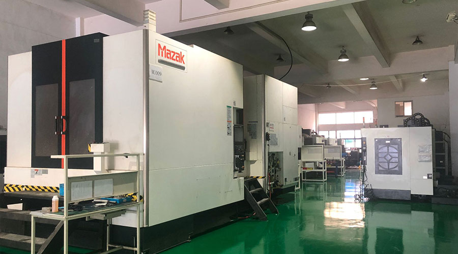 Sheet metal, beryllium, carbon steel, magnesium, 3D printing, precision CNC machining services for heavy equipment, construction, agriculture and hydraulic industries. Suitable for plastics and rare alloys machining. It can turn parts up to 15.7 inches in diameter. Processes include swiss machining,broaching, turning, milling, boring and threading. It also provides metal polishing, painting, surface grinding and shaft straightening services. The production range is up to 50,000 pieces. Suitable for screw, coupling, bearing, pump, gearbox housing, drum dryer and rotary feed valve applications.PTJ will strategize with you to provide the most cost-effective services to help you reach your target,Welcome to Contact us ( [email protected] ) directly for your new project.
Link to this article:How to measure the surface roughness of large parts?
Reprint Statement: If there are no special instructions, all articles on this site are original. Please indicate the source for reprinting:Tungusten,Thanks!^^

