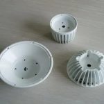
1. Appearance, size and fit of the molded product
1. Defects on the product surface are not allowed: lack of material, burnt, top white, white line, peaking, blistering, whitening (or cracking, breaking), baking, and wrinkles. .
2. Welding mark: Generally, the length of circular perforation weld mark is no more than 5mm, and the length of special-shaped perforation weld mark is less than 15mm, and the weld mark strength can pass the functional safety test. .
3. Shrinkage: Shrinkage is not allowed in obvious areas of the appearance, and slight shrinkage is allowed in unobvious areas (not feeling dents). .
4. Generally, the flatness of small products is less than 0.3mm. If there are assembly requirements, the assembly requirements must be guaranteed.
5. There should be no air lines or material flowers in the obvious appearance, and the product should generally not have air bubbles.
6. The geometrical shape and dimensional accuracy of the product should meet the requirements of the formal and effective mold drawing (or 3D file). The product tolerance should be based on the tolerance principle. The shaft size tolerance is a negative tolerance, and the hole size tolerance is a positive tolerance. The customer has As required, as required.
7. Product wall thickness: The product wall thickness is generally required to be average wall thickness, non-average wall thickness should meet the requirements of the drawing, and the tolerance should be -0.1mm according to the characteristics of the mold.
8. Product coordination: surface shell and bottom shell coordination: the surface misalignment is less than 0.1mm, and there should be no scratching. The holes, shafts and surfaces that have the matching requirements must ensure the matching interval and use requirements.
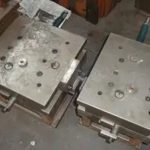
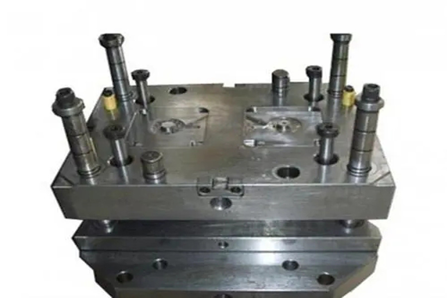
Second, the appearance of the mold
1. The content of the mold nameplate is complete, the characters are clear, and the arrangement is neat.
2. The nameplate should be fixed on the mold foot near the template and the reference angle. The nameplate is reliable and not easy to peel off.
3. The cooling water nozzle should be made of plastic block water nozzle, if the customer requires otherwise, please follow the requirements. 4. The cooling water nozzle should not protrude from the surface of the mold base
5. The cooling water nozzle needs to be processed with counterbore. The counterbore diameter is 25mm, 30mm and 35mm. The orifice is chamfered and the chamfer should be the same. .
6. The cooling water nozzle should be marked for entry and exit.
7. Mark English characters and numbers should be greater than 5/6, and the position should be 10mm directly below the tap. The handwriting should be clear, beautiful, neat, and evenly spaced.
8. Mould accessories should not affect the hoisting and storage of moulds. During installation, there are exposed oil cylinders, faucets, pre-reset mechanism, etc., which should be protected by supporting legs.
9. The mounting of the support leg should be fixed on the mold base with screws passing through the support leg, and the excessively long support leg can be fastened on the mold base with a machined external threaded column.
10. The size of the ejector hole of the mold should meet the requirements of the specified injection molding machine. Except for small molds, one center cannot be used for ejection.
11. The positioning ring should be fixed and reliable. The diameter of the ring is 100mm and 250mm. The positioning ring is 10-20mm higher than the bottom plate. Unless otherwise requested by customers.
12. The external dimensions of the mold should meet the requirements of the designated injection molding machine.
13. For molds with orientation requirements, an arrow should be used to indicate the installation direction on the front template or the rear template. There should be “UP” next to the arrow. The arrow and text are both yellow and the height of the font is 50 mm.
14. The surface of the mold base should not have pits, rust marks, redundant rings, water vapor in and out, oil holes, etc., and defects that affect the appearance.
15. The mold should be easy to hoist and transport, and the parts of the mold must not be disassembled during hoisting, and the hoisting ring must not interfere with the water nozzle, oil cylinder, pre-reset rod, etc.
3. Mold material and hardness
1. The mold base should be a standard mold base that conforms to the standard.
2. Mold forming parts and gating system (core, movable and fixed mold inserts, movable inserts, split cones, push rods, sprue sleeves) are made of materials with performance higher than 40Cr.
3. When molding plastics that are corrosive to the mold, the molded parts should be made of corrosion-resistant materials, or the molding surface should take anti-corrosion measures.
4. The hardness of the moulded parts should not be lower than 50HRC, or the hardness of the surface hardening treatment should be higher than 600HV.
Four, eject, reset, pull out the ferrule, take out
1. The ejection should be smooth, without jamming, and without abnormal sound.
2. The inclined top surface should be polished, and the inclined top surface is lower than the core surface.
3. The sliding parts should be provided with an oil groove, and the surface needs to be nitrided, and the surface hardness after treatment is HV700 or higher.
4. All ejector rods should have stop-rotation positioning, and each ejector rod should be numbered.
5. The ejection distance should be limited by a limit block
6. Standard parts should be used for the return spring, and both ends of the spring should not be polished or cut off.
7. Slider and core-pulling should have stroke limit, small slide is limited by spring, if spring is inconvenient to install, corrugated screw can be used; cylinder core-pulling must have a stroke switch.
8. Generally, inclined guide posts are used for core pulling of the slider, and the angle of the inclined guide post should be 2°~3° smaller than the angle of the locking surface of the slider. If the stroke of the slider is too long, the oil cylinder should be used for drawing.
9. When the end surface of the core-pulling forming part of the cylinder is covered, the cylinder should be equipped with a self-locking mechanism.
10. There should be wear-resistant plates under the large slides with a width of more than 150 mm. The wear-resistant plate material should be T8A. The hardness after heat treatment is HRC50-55. The wear-resistant plate is 0.05-0.1 mm higher than the large surface. Open the oil tank.
11. The ejector rod should not move up and down.
12. Add barbs on the top rod, and the direction of the barbs should be consistent, so that the barbs are easy to remove from the product.
13. The clearance between the ejector pin hole and the ejector pin, the length of the sealing section, and the surface roughness of the ejector pin hole should be in accordance with the requirements of the relevant enterprise standards.
14. The product should be convenient for the operator to remove it.
15. When the product is ejected, it is easy to follow the inclined top, and the top rod should be grooved or etched.
16. The top block fixed on the top rod should be firm and reliable, the non-formed part around the circumference should be processed with a slope of 3°~5°, and the lower periphery should be chamfered.
17. There should be no iron filings in the oil passage hole on the mold base.
18. The end face of the return rod is flat and there is no spot welding. No gasket at the bottom of the embryo head, spot welding.
19. The gate plate of the three-plate mold slides smoothly, and the gate plate is easy to open.
20. Three-plate mold limit rods should be arranged on both sides of the mold installation direction, or pull plates should be added to the mold base to prevent the limit rods from interfering with the operator.
21. The oil circuit and air passage should be smooth, and the hydraulic ejector reset should be in place.
22. An exhaust port should be opened at the bottom of the guide sleeve.
23. There should be no clearance for the positioning pin installation.
5. Cooling and heating system
1, The cooling or heating system should be fully unblocked.
2. The seal should be reliable, the system should not leak under the pressure of 0.5MPa, and it is easy to check and repair.
3. The size and shape of the sealing groove opened on the mold base should meet the requirements of relevant standards.
4. Grease should be applied to the sealing ring when it is placed, and it should be higher than the surface of the mold base after it is placed.
5. Water and oil flow channel separators should be made of materials that are not easily corroded.
6. The front and rear molds should use centralized water supply.
Six, pouring system
1, The gate setting should not affect the appearance of the product and meet the product assembly.
2. The runner section and length should be designed reasonably, and the process should be shortened as much as possible under the premise of ensuring the forming quality, and the cross-sectional area should be reduced to shorten the filling and cooling time. At the same time, the plastic loss of the pouring system should be the least.
3. The part of the three-plate mold runner runner at the back of the front mold should be trapezoidal or semicircular.
4. The three-plate mold has a material breaker on the gate plate, the diameter of the gate entrance should be less than 3 mm, and the ball head has a 3 mm deep step recessed into the gate plate.
5. The ball end pull rod should be reliably fixed, can be pressed under the positioning ring, can be fixed with headless screws, or can be pressed with a pressure plate.
6. Gates and runners should be machined according to the size requirements of the drawings, and manual grinding and polishing machines are not allowed.
7. The point gate gate should be in accordance with the requirements of the specification.
8. There should be an extension at the front end of the runner as a cold slug hole.
9. The Z-shaped inverted buckle of the pulling rod should have a smooth transition.
10. The runner on the parting surface should be round, and the front and rear molds cannot be misaligned.
11. The latent gate on the ejector rod should have no surface shrinkage.
12. The diameter and depth of the cold slug hole for transparent products should meet the design standards.
13. The handle is easy to remove, there is no gate mark on the appearance of the product, and there is no residual handle at the product assembly.
14. For curved hook latent gate, the two parts of the insert should be nitrided, and the surface hardness can reach HV700.
Seven, hot runner system
1. The wiring layout of the hot runner should be reasonable for easy maintenance, and the wiring number should be one-to-one correspondence.
2. The hot runner should be tested for safety, and the insulation resistance to ground should be greater than 2MW.
3. Standard parts should be adopted for temperature control cabinet, hot nozzle and hot runner.
4. The main flow port sleeve is connected with the hot runner with threads, and the bottom surface is in contact with the hot runner for sealing.
5. The hot runner is in good contact with the heating plate or heating rod, and the heating plate is fixed with screws or studs, and the surface fits well.
6. The J-type thermocouple should be used and matched with the temperature control meter.
7. Each group of heating elements should be controlled by thermocouples, and the position of the thermocouples should be reasonably arranged.
8. The nozzle should meet the design requirements.
9. The hot runner should be reliably positioned, at least two positioning pins, or fixed with screws.
10. There should be an insulation pad between the hot runner and the template.
11. The error between the set temperature of the temperature control meter and the actual display temperature should be less than ±5°C, and the temperature control should be sensitive.
12. The cavity and nozzle installation hole should pass through.
13. The hot runner wiring should be bundled and covered with a pressure plate.
14. There are two sockets of the same specification, which should be clearly marked.
15. The control line should be sheathed and not damaged.
16. The structure of the temperature control cabinet is reliable, and the screws are not loose.
17. The socket is installed on the bakelite and cannot exceed the maximum size of the template.
18. The wires must not be exposed outside the mold.
19. All the places where the hot runner or template is in contact with the wires should have rounded transitions.
20. Before the template is assembled, there is no open circuit or short circuit in all circuits.
21. All wiring should be connected correctly, with good insulation performance.
22. After the template is installed and clamped, all circuits should be checked again with a multimeter.
8. Forming part, parting surface, exhaust groove
1. There should be no unevenness, pits, rust and other defects affecting the appearance on the surface of the front and rear molds.
2. The insert is matched with the mold frame, and there should be a clearance of less than 1 mm around the rounded corners.
3. The parting surface is kept clean and tidy. There is no portable grinding wheel to avoid cavities, and the sealing part has no dents.
4. The depth of the exhaust groove should be less than the overflow value of the plastic.
5. The research and distribution of inserts should be in place, with smooth placement and reliable positioning.
6. The inserts, inserts, etc. should be reliably positioned and fixed, the round pieces should be prevented from rotating, and no copper or iron sheets should be placed under the inserts.
7. The end face of the ejector rod is consistent with the core.
8. The forming part of the front and rear molds has no defects such as undercuts and chamfers.
9. The ribs should be pushed out smoothly.
10. For multi-cavity mold products, the left and right parts are symmetrical, and L or R should be indicated. If the customer has requirements for position and size, it should meet customer requirements. Generally, add it where it does not affect the appearance and assembly. The font size is 1/8 .
11. The clamping surface of the mold base should be in place, and more than 75% of the area should be touched.
12. The ejector rods should be arranged closer to the side walls and beside the ribs and bosses, and larger ejector rods should be used.
13. For the same parts, the numbers 1, 2, 3, etc. should be indicated.
14. Each contact surface, penetrating surface, and parting surface should be researched and matched in place.
15. The parting surface sealing part should meet the design standards. 10-20mm for medium-sized molds, 30-50 mm for large molds, and the remaining parts are machined to avoid empty spaces.
16. The skin texture and sandblasting should meet the customer’s requirements evenly.
17. For products with requirements for appearance, the screws on the products should have anti-shrink measures.
18. Jack pipes should be used for screw columns with a depth of more than 20 mm.
19. The wall thickness of the product should be uniform, and the deviation should be controlled below ±0.15 mm.
20. The width of the ribs should be less than 60% of the wall thickness of the exterior surface
21. The insert cores on the inclined roof and the slider should have a reliable fixing method.
22. The front mold is inserted into the rear mold or the rear mold is inserted into the front mold, and the sides should be locked with inclined planes and machined to avoid air.
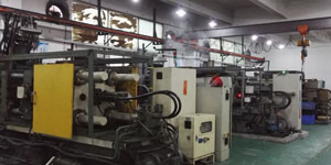
Nine, injection molding production process
1, The mold should have the stability of injection molding production and the repeatability of process parameter adjustment within the range of normal injection molding process conditions.
2. The injection pressure during mold injection production should generally be less than 85% of the injection molding machine’s rated maximum injection pressure.
3. The injection speed of the injection molding production of the mold, the injection speed of the three-quarter stroke is not less than 10% of the rated maximum injection speed or more than 90% of the rated maximum injection speed.
4. The holding pressure of the mold during injection molding should generally be less than 85% of the actual maximum injection pressure.
5. The clamping force of the mold during injection molding production should be less than 90% of the rated clamping force of the applicable model.
6. During the injection molding production process, the product and the nozzle material should be taken out easily and safely (the time is generally not more than 2 seconds each).
7. For molds with inserts, the inserts are easy to install and the inserts are fixed reliably during production.
10. Packaging and transportation
1 The mold cavity should be cleaned and sprayed with anti-rust oil.
2. The sliding parts should be lubricated.
3. The inlet of the sprue bushing should be sealed with grease.
4. The mold should be equipped with a clamping piece, and the specifications meet the design requirements.
5. Spare parts and wearing parts should be complete, with a detailed list and the name of the supplier
6. Sealing measures should be taken to prevent foreign matter from entering the mold water, liquid, gas, and electrical inlets and outlets;
7. Spray paint on the outer surface of the mold, as required by the customer.
8. Moulds should be packaged in moisture-proof, waterproof, and bump-proof packaging, as required by customers.
9. Mold product drawings, structural drawings, cooling and heating system drawings, hot runner drawings, spare parts and mold material supplier details, operating instructions, mold test reports, factory inspection certificates, and electronic documents should all be complete.
Please keep the source and address of this article for reprinting: The most complete mold acceptance standard in history!
Minghe Die Casting Company are dedicated to manufacture and provide quality and high performance Casting Parts(metal Die Casting parts range mainly include Thin-Wall Die Casting,Hot Chamber Die Casting,Cold Chamber Die Casting),Round Service(Die Casting Service,Cnc Machining,Mold Making,Surface Treatment).Any custom Aluminum die casting, magnesium or Zamak/zinc die casting and other castings requirements are welcome to contact us.
Under the control of ISO9001 and TS 16949,All processes are carried out through hundreds of advanced die casting machines, 5-axis machines, and other facilities, ranging from blasters to Ultra Sonic washing machines.Minghe not only has advanced equipment but also have professional team of experienced engineers,operators and inspectors to make the customer’s design come true.

Contract manufacturer of die castings. Capabilities include cold chamber aluminum die casting parts from 0.15 lbs. to 6 lbs., quick change set up, and machining. Value-added services include polishing, vibrating, deburring, shot blasting, painting, plating, coating, assembly, and tooling. Materials worked with include alloys such as 360, 380, 383, and 413.
Zinc die casting design assistance/concurrent engineering services. Custom manufacturer of precision zinc die castings. Miniature castings, high pressure die castings, multi-slide mold castings, conventional mold castings, unit die and independent die castings and cavity sealed castings can be manufactured. Castings can be manufactured in lengths and widths up to 24 in. in +/-0.0005 in. tolerance.
ISO 9001: 2015 certified manufacturer of die cast magnesium, Capabilities include high-pressure magnesium die casting up to 200 ton hot chamber & 3000 ton cold chamber, tooling design, polishing, molding, machining, powder & liquid painting, full QA with CMM capabilities, assembly, packaging & delivery.
ITAF16949 certified. Additional Casting Service Include investment casting,sand casting,Gravity Casting, Lost Foam Casting,Centrifugal Casting,Vacuum Casting,Permanent Mold Casting,.Capabilities include EDI, engineering assistance, solid modeling and secondary processing.
Casting Industries Parts Case Studies for: Cars, Bikes, Aircraft, Musical instruments, Watercraft, Optical devices, Sensors, Models, Electronic devices, Enclosures, Clocks, Machinery, Engines, Furniture, Jewelry, Jigs, Telecom, Lighting, Medical devices, Photographic devices, Robots, Sculptures, Sound equipment, Sporting equipment, Tooling, Toys and more.
What Can we help you do next?
∇ Go To Homepage For Die Casting China
→Casting Parts-Find out what we have done.
→Ralated Tips About Die Casting Services
By Minghe Die Casting Manufacturer |Categories: Helpful Articles |Material Tags: Aluminum Casting, Zinc Casting, Magnesium Casting, Titanium Casting, Stainless Steel Casting, Brass Casting,Bronze Casting,Casting Video,Company History,Aluminum Die Casting |Comments Off
Link to this article:The most complete mold acceptance standard in history!
Reprint Statement: If there are no special instructions, all articles on this site are original. Please indicate the source for reprinting:Tungusten,Thanks!^^