In the processing of titanium alloy camera brackets, a three-axis machine tool is used to cooperate with the turntable. By controlling the clamping deformation of the parts, the auxiliary alignment datum is added, the cutting tools are reasonably selected, and the deformation in the processing is reasonably controlled. The processing of all holes is completed in one clamping. The high-efficiency, low-cost and high-quality machining of high-precision coaxial holes of thin-walled titanium alloy parts is realized.
The camera bracket is a very important part in the shooting part of the satellite camera. It is mainly used to precisely install the lens of the satellite camera and make the camera rotate 360°. Restricted by the conditions of use and the environment, the parts are required to have a lighter structure and high strength when they meet the requirements.
The part material is titanium alloy, which has the characteristics of high strength, good corrosion resistance, high heat resistance and relatively light weight. The parts are thin-walled structural parts, which are prone to deformation during clamping and processing, which seriously affects the accuracy of the parts.
1. Part structure characteristics and technical parameters
Figure 1 shows the U-shaped camera stand. The external dimensions of the parts are 516mm×407mm×227mm, the wall thickness is 4mm, the whole is U-shaped structure and most of them are cavities. The machining accuracy of the three holes are as pictures
The verticality of two φ100mm inner holes is required to be 0.02mm.
a) Structure size
b) The physical object
Figure 1 U-shaped camera bracket
2. Material performance and cutting performance analysis
The cutting performance of titanium alloy is poor, mainly due to its poor thermal conductivity, resulting in high cutting temperature, thus reducing tool life. The small deformation coefficient during cutting of titanium alloy increases the sliding friction distance of chips on the rake face and accelerates tool wear.
The modulus of elasticity of titanium alloy is small, and it is easy to produce bending deformation under the action of radial force during processing, which will cause vibration, increase the wear of the tool and affect the accuracy of the parts. Due to the strong chemical affinity of titanium alloy to tool materials, under the conditions of high cutting temperature and large cutting force per unit area, the tool is prone to adhesion and wear.
3. Process design
The machining process is divided into two stages: rough machining and finishing. In order to eliminate the work hardening and the internal stress of the material, two heat treatments are arranged in the middle to reduce the influence of the deformation of the parts on the machining accuracy. Technological process: rough milling contour→stress relief annealing→finish milling contour and inner cavity→artificial aging plus cooling and heating cycle→boring all inner holes.
4. Analysis of processing difficulties
After analysis, the processing difficulties of the titanium alloy camera holder are as follows.
1) The external dimensions of the parts are large, and it is not easy to cut.
2) The camera bracket is a typical thin-walled part, which is prone to deformation during clamping and processing.
3) The span of the two coaxial holes is 516mm, and the coaxiality is required to be 0.01mm. The accuracy of the inner hole in the picture is high, and it is not easy to guarantee the accuracy requirements.
4) The tolerance level of the inner hole of the largest picture reaches IT4 level, the depth is 80mm, and the perpendicularity to the axis of the φ100mm inner hole is 0.02mm, and the dimensional accuracy is not easy to guarantee.
5. Measures taken
Take the following measures for processing difficulties.
1) In order to meet the requirements of machining accuracy, combined with the structural characteristics.
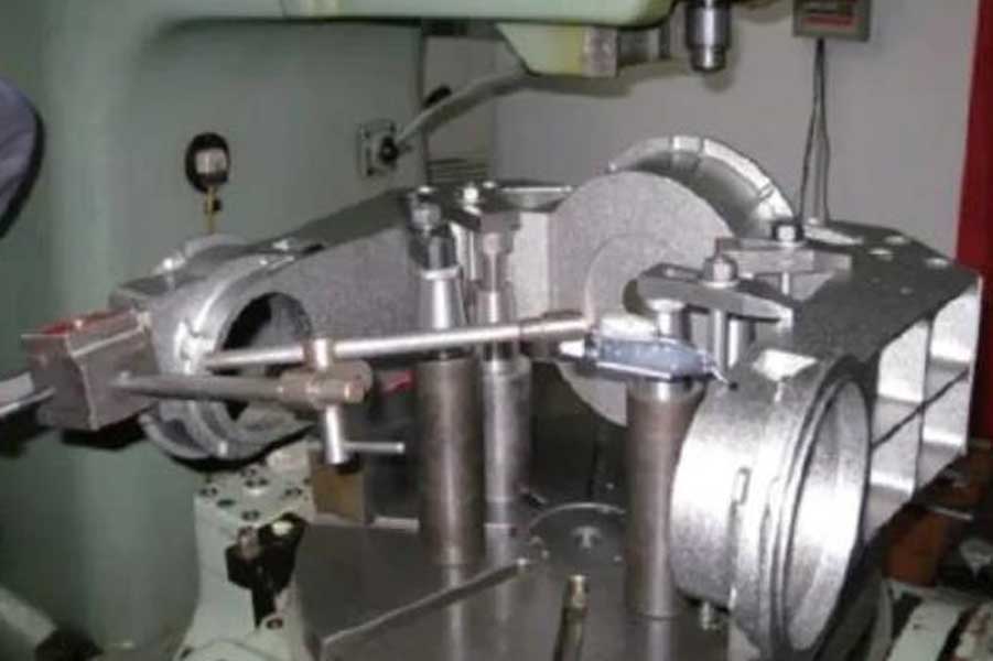
the T4163 coordinate boring machine is selected for machining, and at the same time, the turntable is used to complete the machining of all holes in one clamping process to reduce the error caused by multiple clamping. The clamping method of the U-shaped camera bracket is shown in Figure
2) Measures to ensure the dimensional accuracy of the inner hole.
When controlling the dimensional accuracy of the inner hole, in order to ensure the roundness and dimensional stability of the parts, a dynamic balance boring head and a diamond blade are used for processing. The degree of flatness of the reference surface is guaranteed. The flatness of the test is 0.005mm, which basically reaches the upper limit of the accuracy of the machine tool.
Using the turning accuracy of the machine tool turntable, plus the auxiliary alignment method, the verticality of the inner hole of the picture and the reference plane is guaranteed to be 0.02mm. At the same time, when boring the inner hole, all inner holes are left with a 0.4mm margin, and the method of removing the machining margin with multiple equal margins is used to observe the size change and adjust the removal amount to ensure the hole diameter accuracy and the inner hole surface roughness requirements .
3) The main measures to control the internal stress deformation, clamping deformation and processing deformation of the parts are as follows:
① Control internal stress and deformation.
The parts are divided into roughing, finishing and stress relief annealing, artificial aging and high and low temperature heating and cooling cycles to minimize the generation of internal stress.
②Control clamping deformation.
Figure 3 shows the real-time monitoring measures for the deformation of the U-shaped camera bracket. To control the size of the clamping force, the dial indicator is used for multi-point printing, and the dial indicator and the compaction point are corresponded one by one with the method of three-point small torque compaction, and the method of multiple cycles of gradual compaction is adopted to ensure the freedom In the state, the x-axis and y-axis values of each clamping point dial indicator remain unchanged to minimize clamping deformation, while ensuring uniform force and reliable clamping.
③ Use cooling-based water-soluble emulsion for cooling, while controlling the indoor temperature to ensure the room temperature (20±2) ℃.
so as to control the processing thermal deformation; by selecting reasonable tool materials, angles and cutting parameters, minimize the processing In the cutting force, thereby reducing the deformation generated during processing.
4) Ensure the coaxiality requirements.
Fixing a datum block on the turntable is equivalent to adding an auxiliary alignment datum. After processing the inner hole of one picture, rotate 180° to process the inner hole of another picture. The rotation angle is adjusted with the reference block with a dial indicator to eliminate the angle error when the turntable is turned and rotated to the maximum extent, and then use the extension rod to configure Align the inner hole of the processed picture with a dial indicator to ensure the coaxiality requirements of the parts.
5) Control tool vibration during processing.
①Measures to control forced vibration: stay away from the source of vibration, avoid vibration with other machine tools and the formation of resonance between machine tools. ②Measures to control self-excited vibration: It is to solve the matching degree of workpiece rigidity, tool rigidity and cutting force during processing.
In order to ensure the final geometric accuracy of the parts and ensure that the impact of clamping deformation on the parts is minimized, the matching cutting tools, cutting parameters and tool angles should be selected without increasing the rigidity of the workpiece, that is, to reduce the depth of cut, Reduce the cutting speed, choose a reasonable feed rate and increase the rigidity of the tool.
6. Product quality inspection
After the U-shaped camera bracket is processed, the main technical indicators are tested with a three-coordinate measuring instrument, and the results all meet the requirements of the drawing. The key data detection results of the three-coordinate measuring instrument are shown in Table 1.
7. Concluding remarks
Through the processing of titanium alloy camera brackets, certain experience has been accumulated in the processing of large-span coaxial holes of U-shaped parts and the prevention of deformation of thin-walled parts, which has certain reference significance for processing such large titanium alloy parts in the future.
Link to this article:Precision Machining of High-precision Coaxial Holes in Titanium Alloy Camera Bracket
Reprint Statement: If there are no special instructions, all articles on this site are original. Please indicate the source for reprinting:https://www.cncmachiningptj.com/,thanks!
 3, 4 and 5-axis precision CNC machining services for aluminum machining, beryllium, carbon steel, magnesium, titanium machining, Inconel, platinum, superalloy, acetal, polycarbonate, fiberglass, graphite and wood. Capable of machining parts up to 98 in. turning dia. and +/-0.001 in. straightness tolerance. Processes include milling, turning, drilling, boring, threading, tapping, forming, knurling, counterboring, countersinking, reaming and laser cutting. Secondary services such as assembly, centerless grinding, heat treating, plating and welding. Prototype and low to high volume production offered with maximum 50,000 units. Suitable for fluid power, pneumatics, hydraulics and valve applications. Serves the aerospace, aircraft, military, medical and defense industries.PTJ will strategize with you to provide the most cost-effective services to help you reach your target,Welcome to Contact us ( [email protected] ) directly for your new project.
Link to this article:Precision Machining of High-precision Coaxial Holes in Titanium Alloy Camera Bracket
Reprint Statement: If there are no special instructions, all articles on this site are original. Please indicate the source for reprinting:Tungusten,Thanks!^^

